
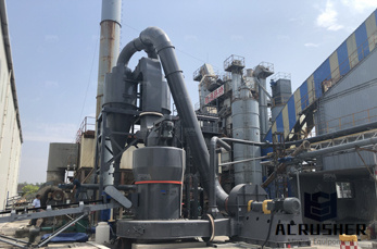
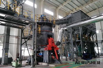
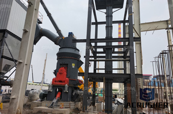
how to draw a process plant cash flow diagram manufacturer Grasping strong production capability, advanced research strength and excellent service, Shanghai how to draw a process plant cash flow diagram supplier create the value and bring values to all of customers.
 WhatsApp)
Jun 02, 2017· In this article, I have compiled a list of 3 free websites to draw Process Flow Diagram Online.With these websites, you can design PFDs for factories and plants. There are symbols for every component required to setup factory or manufacturing plant like valves, instruments like temp controller, transducer, etc., heat exchangers, vessels, etc.
A piping and instrumentation diagram (P&ID), sometimes called piping flow diagram or process flow diagram, is a kind of schematic drawing, which shows the sequence of process equipments and instrumentations. P&ID is used for erection and commission as well as during maintenance of a process plant.
Flowchart Maker and Online Diagram Software. diagrams (formerly draw.io) is free online diagram software. You can use it as a flowchart maker, network diagram software, to create UML online, as an ER diagram tool, to design database schema, to build BPMN online, as a circuit diagram maker, and more. draw.io can import .vsdx, Gliffy™ and Lucidchart™ files .
financing—changes in debt, loans, and dividends are accounted for in cash. Hence, a cash flow chart is a visual diagram that shows the flow of the movement of the cash entailed by a company, which is a vital component to be able to keep track of expenditures, prevent errors, and could also save money.
Draw Layout of water treatment plant and explain functions of each unit. OR Draw a flow diagram showing components of water. Follow via messages; Follow via email; ... Clari Floccurator • In this unit two process are done i.e. Flocculation and sedimentation. • Flocculation Floc are formed and in sedimentation Floc get settleddown.
Jul 27, 2017· A flow chart is a diagram that demonstrates a process. Boxes containing explanatory data are connected by arrows representing the directional flow of the process. A cash flow chart, which shows you where your money is going, can help you see .
This PFD example is created using Edraw vector drawing software enhanced with PID solution. It shows the main process of waste water treatment visually.
This chapter covers different types of chemical process diagrams, how these diagrams represent different scales of process views, one consistent method for drawing process flow diagrams, the information to be included in a process flow diagram, and the purpose of operator training simulators and recent advances in 3-D representation of different chemical processes.
A process flow diagram (PFD) is a diagram used in chemical and process engineering to indicate the general flow of plant processes and equipment. Chemical and Process Engineering Solution from the Industrial Engineering Area of ConceptDraw Solution Park is a unique tool which contains variety of predesigned process flow diagram symbols for easy ...
Process diagrams can be broken down into two major categories: process flow diagrams (PFDs) and process and instrument drawings (P&IDs), sometimes called piping and instrumentation drawings. Process Flow Diagram is a simple illustration that uses process symbols to describe the primary flow path through a unit.
Sep 26, 2017· System flow diagrams, also known as process flow diagrams or data flow diagrams, are cousins to common flow charts. In a system flow diagram, the goal is to present a visual representation of some component of the business model, such as a standard customer/clerk transaction at a sandwich shop window.
15.10 Process flow diagram (PFD) and piping and instrumentation diagrams This section is intended for convenience of use and pattern of follow-up and also guidance. Also, it indicates the check points to be considered by the process engineers for assurance of fulfilment of prerequisitions at any stage in the implementation of process plant ...
The Present Value of the cash flows can be calculated by multiplying each cash flow with a Discount Rate. Present Value cash flow flow calculator; Cash Flow Diagram - Investment Transaction. An investment transaction starts with a negative cash flow when the investment is done - and continuous with positive cash flows when receiving the pay backs.
A Process Flow Diagram (PFD) is a diagram which shows the relationships between the main components in a system. Process Flow Diagrams are widely used by engineers in chemical and process engineering, they allows to indicate the general flow of plant process streams and equipment, helps to design the petroleum refineries, petrochemical and chemical plants, natural gas processing .
AutoCAD Plant 3D / P&ID Ideas ... (Process Flow Diagrams) should be part of Plant3D ... I have to draw a Process Flow Diagram or PFD at the beginning of every project, even proposals. Having the PFD linked to the P&ID would be a plus, but not absolutely necessary.
A Process Flow Diagram (PFD) is a diagram which shows the relationships between the main components in a system. Process Flow Diagrams are widely used by engineers in chemical and process engineering, they allows to indicate the general flow of plant process streams and equipment, helps to design the petroleum refineries, petrochemical and chemical plants, natural gas processing .
A flow process chart is a chart showing the sequence of the flow of a product by way of recording all activities/events under review with appropriate symbols. This chart is similar to operation process chart with the difference that it utilizes symbols of operation, .
Drawing a Cash Flow Diagram. The cash flowdiagram shows when all cash flows occur. Look at Figure 2-7 and the $100 positive cash flowat the end of period 2. Fromthe time line one can see that this cash flow can also be described as occurring at the beginning of period 3. Thus, in a CFD the end of period t is the saI}letime as the beginning of ...
A Process Flow Diagram (PFD) is a diagram which shows the relationships between the main components in a system. Process Flow Diagrams are widely used by engineers in chemical and process engineering, they allows to indicate the general flow of plant process streams and equipment, helps to design the petroleum refineries, petrochemical and chemical plants, natural gas processing .
Mar 02, 2018· How to Read Process Flow Diagrams (PFDs/PFS) - A Complete Tutorial - Duration: 9:57. HardHat Engineer 21,355 views. 9:57. Piping interview question & Answers | Piping Analysis - .
Process flow diagrams (PFDs) are used in chemical and process engineering. These diagrams show the flow of chemicals and the equipment involved in the process. Generally, a Process Flow Diagram shows only the major equipment and doesn't show details. PFDs are used for visitor information and new employee training.
Mar 12, 2019· A Process Flow Diagram (PFD) is a type of flow sheet that illustrates the relationships between major equipment within the project. PFD's specify flow rates, temperature, pressure and other ...

Aug 28, 2011· The HACCP team should confirm the processing operation against the flow diagram during all stages and hours of operation and amend the flow diagram where appropriate. If you want to recap on the HACCP Basics (including flow process charts) check out our An Introduction to HACCP express learning module by clicking here.

Piping and Instrumentation Diagram (P&ID), which is also known as process and instrumentation diagram, is a schematic illustration in the process industry showing the piping of the process flow together with the installed equipment and instrumentation through graphical symbols. It shows how industrial process equipment is interconnected by a ...
WhatsApp)