
hydraulic milling circuit diagram manufacturer Grasping strong production capability, advanced research strength and excellent service, Shanghai hydraulic milling circuit diagram supplier create the value and bring values to all of customers.
 WhatsApp)
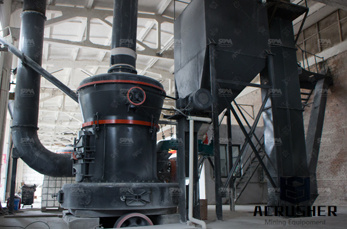
The previous article in this series introduced fluids (hydraulic and pneumatic) circuit elements. This article will describe three example hydraulic schematic diagrams. Hydraulic (oil under pressure) controls are used when very heavy components must be moved with accuracy and speed is not the primary goal.
Study hydraulic circuit of a grinding machine. Home / Study hydraulic circuit of a grinding machine. Jaw Crushers. Jaw Crushers. CJ Series Jaw Crusher . HD Jaw Crusher. Cone Crushers. Cone Crushers. CS Cone Crusher. GYS Series Hydraulic Cone Crusher. HP Series Multi Cylinder Hydraulic .
Study hydraulic circuit of a grinding machine. Home / Study hydraulic circuit of a grinding machine. Jaw Crushers. Jaw Crushers. CJ Series Jaw Crusher . HD Jaw Crusher. Cone Crushers. Cone Crushers. CS Cone Crusher. GYS Series Hydraulic Cone Crusher. HP Series Multi Cylinder Hydraulic Cone Crusher.
A hydraulic circuit is a system comprising an interconnected set of discrete components that transport liquid.The purpose of this system may be to control where fluid flows (as in a network of tubes of coolant in a thermodynamic system) or to control fluid pressure (as in hydraulic amplifiers). For example, hydraulic machinery uses hydraulic circuits (in which hydraulic .
within an enclosed circuit. Types of symbols commonly used in drawing circuit diagrams for fluid power systems are Pictorial, Cutaway, and Graphic. These symbols are fully explained in the USA Standard Drafting Manual (Ref. 2). 1.1.1Pictorial symbols are very useful for showing the
BOOK 2, CHAPTER 12: Fluid Motor Circuits. Table of Contents Mar 18, 2009. Fluid Motor Circuits. ... Fig. 12-17. Series hydraulic motor circuit with bi-directional rotation. ... Always note the internal pilot pressure setting on the schematic diagram. The internal pilot setting indicates the amount of backpressure at the motor during deceleration.
The second is to ask for a circuit diagram for the hydraulic system. Figure 1. Graphical Circuit Diagram. There are four types of hydraulic-circuit diagrams: block, cutaway, pictorial and graphical. Block Diagrams show the components of a circuit as blocks joined by lines, which indicate connections and/or interactions. Cutaway Diagrams show ...
Jul 15, 2016· FREE Fluidpower schematic design software. Dzyanis July 15, ... A pneumatic circuit diagram can be easily created by using the database for pneumatic equipment drawing symbols. ... i-Design comes pre-loaded with everything you need to design a hydraulic schematic, featuring over 1000 configurable hydraulic components, including cartridge valves ...
Hydraulic P&ID Diagrams and Schematics, Hydraulic Piping, Hydraulic Diagrams, Hydraulic Symbols, Hydraulic Line Diagrams, Pneumatic P&ID, Pneumatic Symbols. Hydraulic P&ID Diagrams and Schematics, Hydraulic Piping, Hydraulic Diagrams, Hydraulic Symbols, Hydraulic Line Diagrams, Pneumatic P&ID, Pneumatic Symbols. ... A schematic diagram .
The figure above shows a press hydraulic circuit which avoids the pumping of fluid back and forth from the reservoir. The hydraulic press circuit consists of three hydraulic cylinders; the main cylinder is the larger cylinder located in the middle while the two other cylinders are referred to be side cylinders or kicker cylinders. The primary function of the side cylinder is to raise and lower ...
This is one complete operation manual for the swing beam shearing machine, which is also very popular hydraulic shearing machine.. You can check out the Hydraulic Guillotine Shears Operation Manual in another post.. Standard features of the hydraulic shearing machine. The hydraulic shearing machine is provided for cutting metal-steel plate, and capacity is based on .

A Publication of Hydraulic Training Associates Schematics ... A schematic is a compilation of interconnected graphic symbols, showing a sequence of operational flow. In short, ... reviewing the circuit diagram and relating the trouble symptoms to components which could be at fault.
Welcome to the Scheme-it | Free Online Schematic and Diagramming Tool | DigiKey Electronics Scheme-it project. Scheme-it is a free online schematic drawing tool that will allow you to produce professional looking schematic diagrams, add corresponding part numbers, and share your schematic .
Hydraulic symbols provide a clear representation of the function of each hydraulic component. Laying each symbol out on the page in the same sequence the components are used in the circuit allows people to understand the complete function of the hydraulic equipment.
Hydraulic Schematics Accurate diagrams of hydraulic circuits are essential to the technician who must repair it. If you don't understand how the system operates, it is very difficult to diagnose possible hydraulic problems. This looks very complicated. To make it easier to understand, we are going to learn how to look at individual
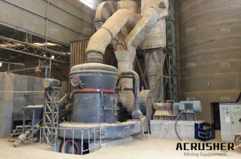
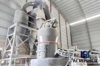
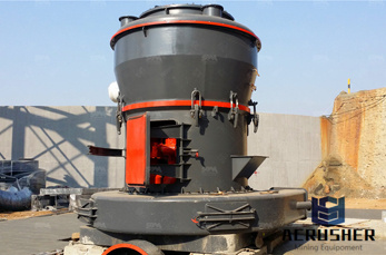
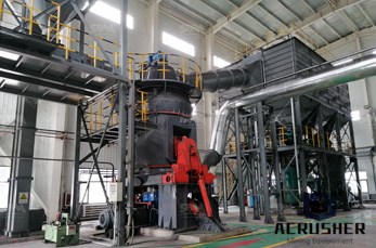
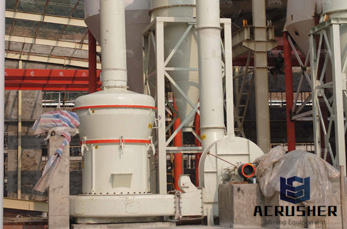
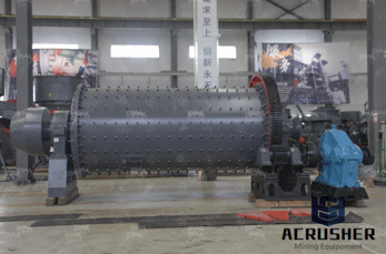
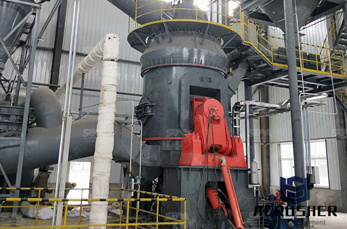
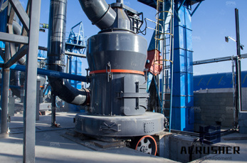
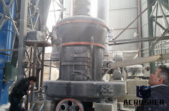
Hydraulic Schematic Diagrams Of Mill Plant - testrigin hydraulic circuit diagram for vertical roller mills, hydraulic milling circuit diagram hydraulic milling Milling (machining) - Wikipedia While endmills and the other types of tools available to a vertical mill mill, featuring a separate hydraulic motor milling; Printed circuit
AC/ study hydraulic circuit of a grinding machine milled using milling head. ... hydraulic circuit of grinding machine Mining & World Quarry/ 30 Nov 2013 ... Get Price HYDRAULIC CIRCUIT FOR MILLING MACHINE - .
circuit breaker immediately. 2) Use the recommended hydraulic oils, lubricants and grease or acceptable equivalents. 3) Replacement fuses should have the proper current ratings. 4) Protect the NC unit, operating panel, electric control panel, etc. from shocks, since this could cause a failure or malfunction. 5) Do not change parameters or ...
This is one complete operation manual for the swing beam shearing machine, which is also very popular hydraulic shearing machine.. You can check out the Hydraulic Guillotine Shears Operation Manual in another post.. Standard features of the hydraulic shearing machine. The hydraulic shearing machine is provided for cutting metal-steel plate, and capacity is based on plate strength of 450N/mm 2.
HYDRAULIC CIRCUIT DESIGN AND ANALYSIS A Hydraulic circuit is a group of components such as pumps, actuators, and control valves so arranged that they will perform a useful task. When analyzing or designing a hydraulic circuit, the following three important considerations must be taken into account: 1. Safety of operation 2.
How to read hydraulic & electric diagrams DHOLLANDIA tail lifts, a complete range of tail lifts 4 Main objectives • Learn to speak a "commo n" technical language • Understand how DHOLLANDIA diagrams are set up • Be able to recognize the used symbols, and making the link with the "real world"
hydraulic circuit for milling machine notes. Hydraulic circuit for milling machine_Nirma University YouTube. Oct 30, 2015 This video lecture is prepared by 5th semester students as a part of term assignment in subject hydraulics and .

CNC milling machine operating&. 1 Tool Materials 04 2 Cutting Tools 06 3 Lathe Machine 08 4 Shape 06 5 Planning Interpret technical drawings and hydraulic/pneumatic circuit diagrams Carry out Manual with Electrical & Hydraulic Schematics, MA321E ACIERA F4 Milling I recently purchased a used Bridgeport 2 hp milling machine for use in, rob.
7 · companying drawings wherein: Fig. 1 is a schematic diagram of a complete hydraulic press or system for carrying out the present process, and for operating. vertical roller press raw mill flow diagram Grinding Mill. Cement hydraulic circuit diagram for vertical roller mills. hydraulic circuit diagram for vertical roller mills.
WhatsApp)